I had some time home last week (and decent weather!) to work more on the auxiliary electrical system for the WK2. As you’ve seen previously, I built and installed a 4-switch panel in the driver dashboard area to control lighting throughout the Jeep. With 18-7 fire alarm wire I made a loom to get back to a control/relay box that I was building for the rear trunk area to house the electrical components of the system. I ran out of time to work on the control box until a recent work trip, so I had products delivered to the hotel and began constructing the main brain of project.
Hardware used:
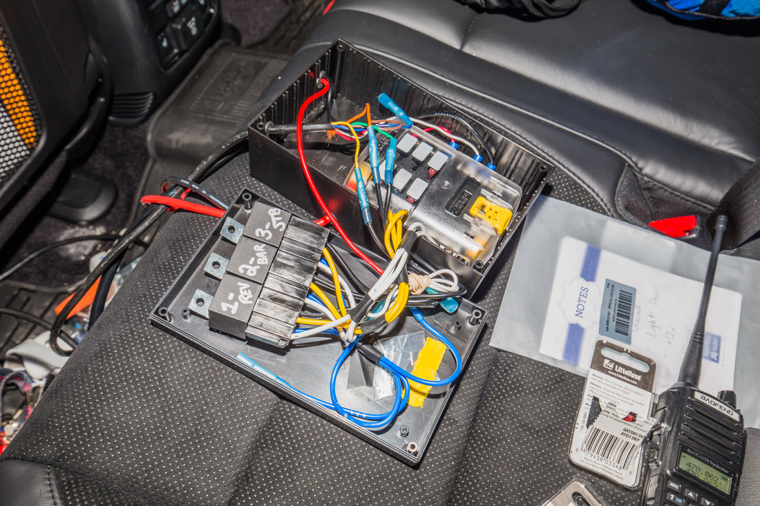
- PI Manufacturing Project Box (ABS) – 7.6” x 4.51” x 2.95”
- Blue Sea Systems 5025 6 Blade Fuse Block
- Rigid Industries 40312 Strobe Flasher
- 4x 12v Relays (30A)
- 6A Blue Ox Saturn Diode Pack
- Misc. heat-shrink connectors
It was a tossup as to what project box would fit my components, but using Google SketchUp I built a few examples to see what the right option would be; even despite doing this I was still nervous that I got it right. Upon the delivery I breathed a sigh of relief as everything fit. Trimming and labeling the wires of the relay harnesses, I crimped my connectors and installed them to the Blue Sea Systems fuse panel accordingly. Labeling the “trigger” and “+12v” lead of the harness, I got everything ready for the installation of the lights themselves. With the interest of being able to remove the fuse panel, strobe controller, and relays from the box, but have them be secure and organized in the mean time, I used 3M adhesive Velcro to hold them to the project box itself. With everything installed and fitment checked, I removed the components and drilled out the sides of the project box for the 8AWG wire leads from the battery, and left two holes in the side for the 18-6 control loom and aux. lighting wiring.
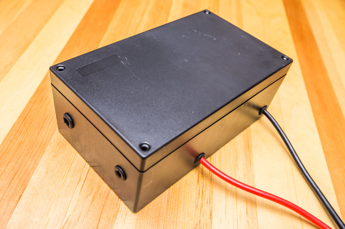
The Project Box:
Once it had the grommets installed and the leads were crimped and heat shrunk, I brought the box out to the Jeep and fished the fire alarm wire out from under the rear bench seats where I had stored it in April when the switch panel was installed. Pulling the 18-6 wire through the grommet in the side of the project box, I went to work crimping and heat-shrinking the switch wires to the relay trigger leads and the +12v and ground switch wires to the Blue Sea fuse system, thereby activating the power and LEDs on the switch panel itself.
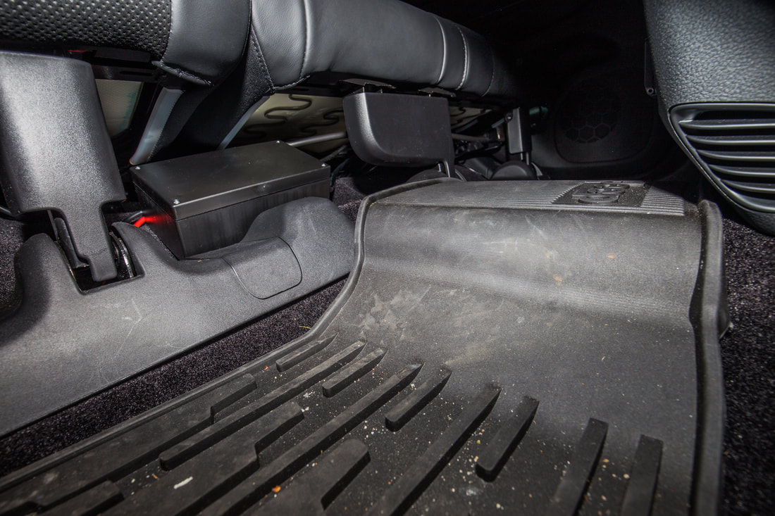
Once the switch leads were heat shrunk and everything was tucked away, I nestled the box itself under the rear bench and used HD Velcro to hold it in place. It ended up being a little further to the passenger side than the photo shows, but it is in a place and is small enough that the bench portions can fold completely flat without coming into contact with the control box. I ran the +12v lead/ground from the battery under the bench hardware trim piece, then under the OEM floor mat and into the battery compartment. It worked flawlessly and is VERY hard to find if you’re not looking for it. I might someday heat shrink that cable too, but for now they’re simply red and black as they run under the flooring. I ran some wiring out of the control box to my multimeter and then the light bar that’s going on the roof (install write-up to come) and was pleased to see that the switches activate each relay appropriately, and the light functions without issue.
One step closer! Next up will be the aux. lighting installations themselves.


