I was home this weekend between work trips, the last two weeks in Orlando and Vegas, the next two in Northwest Arkansas and then Orlando again… This left a very narrow window to get any work done on the Jeep, but Rob and I had anticipated the winch mount and winch having arrived by then… Unfortunately, they hadn’t, so we decided to move forward with another project I had been working on.
One of the most important things for me in vehicles is visibility. The TJ has a LOT of LED lighting, strobes, etc. - so the plan for the WK2 was bound to be pretty intricate as well. First step for any additional lighting is figuring out how it’s going to be controlled, and from where it’s going to be controlled. After Googling a fair amount of options, seeing if anyone had built vehicle-specific panels, I went ahead with my initial plan to install a switch panel to the lower left side of the steering column. There was a great write-up by a guy on JeepForum a few years ago that followed along the same lines as my idea.
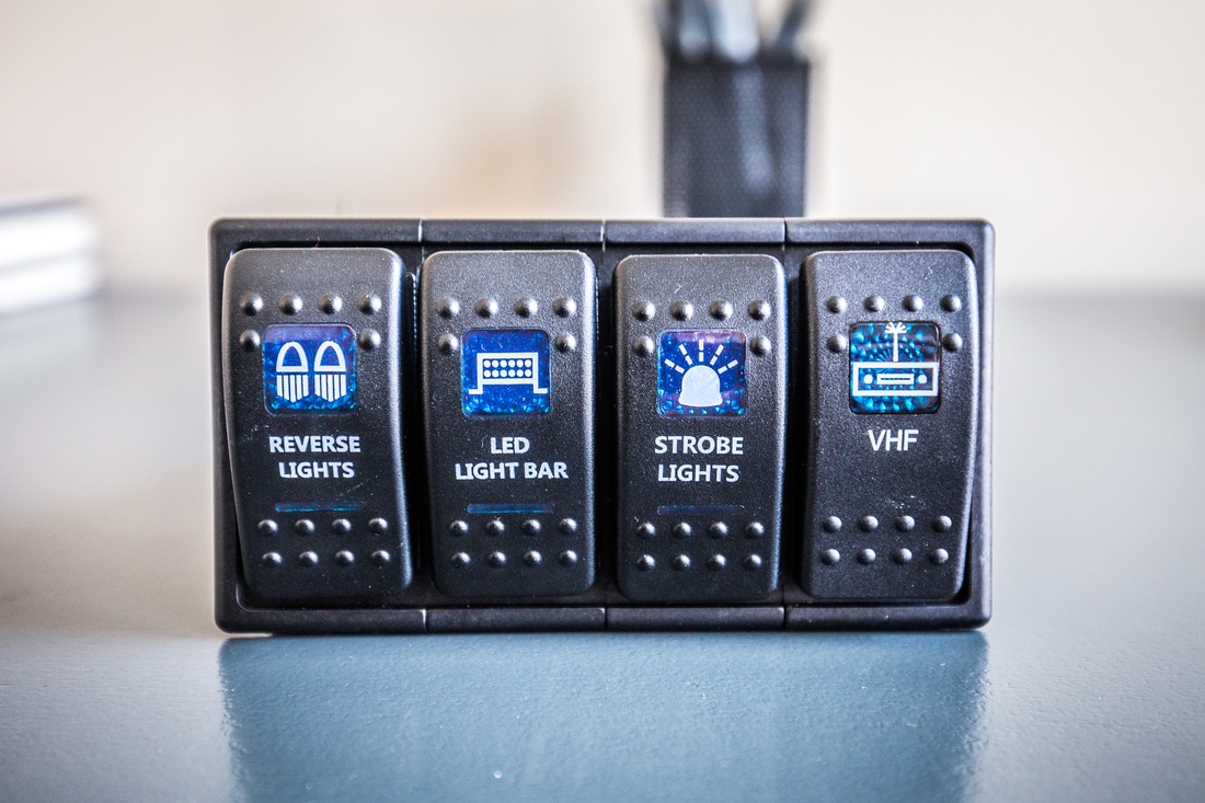
I wanted/needed to keep the switches refined and purposeful, so I had to decide which each of the four Contura switch spaces would control. For me, reverse light is hugely important… second to that is forward facing light, so recessed driving lights or some kind of LED bar will get a spot. Third up in my mind is a strobe light system, as I’ve spent many years with one in the TJ and often find myself pulling over to help people on the side of the road, or utilizing them for other situations in bad weather and the like. Spot 4 then became a catch-all, or an expansion slot.
So:
Switch 1: Reverse LED Lights
Switch 2: LED Bar (likely roof mounted)
Switch 3: LED Strobe System
Switch 4: For the mean time, VHF radio power.
With a quick Amazon order for switches, wiring, heat-shrink crimp connectors, and the 4-space mount, I got to work. The VHF switch cover was from eBay for an extra seven bucks.
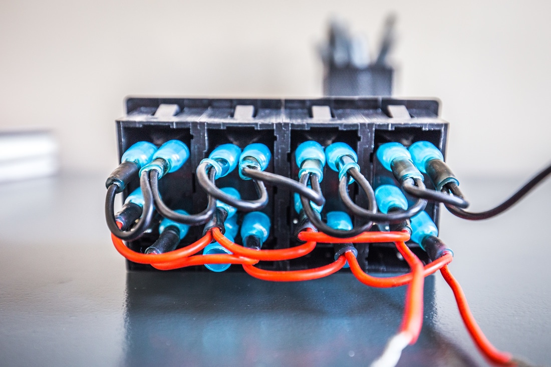
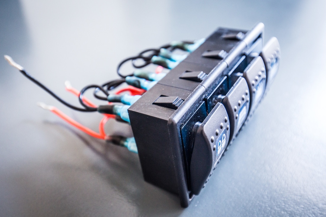
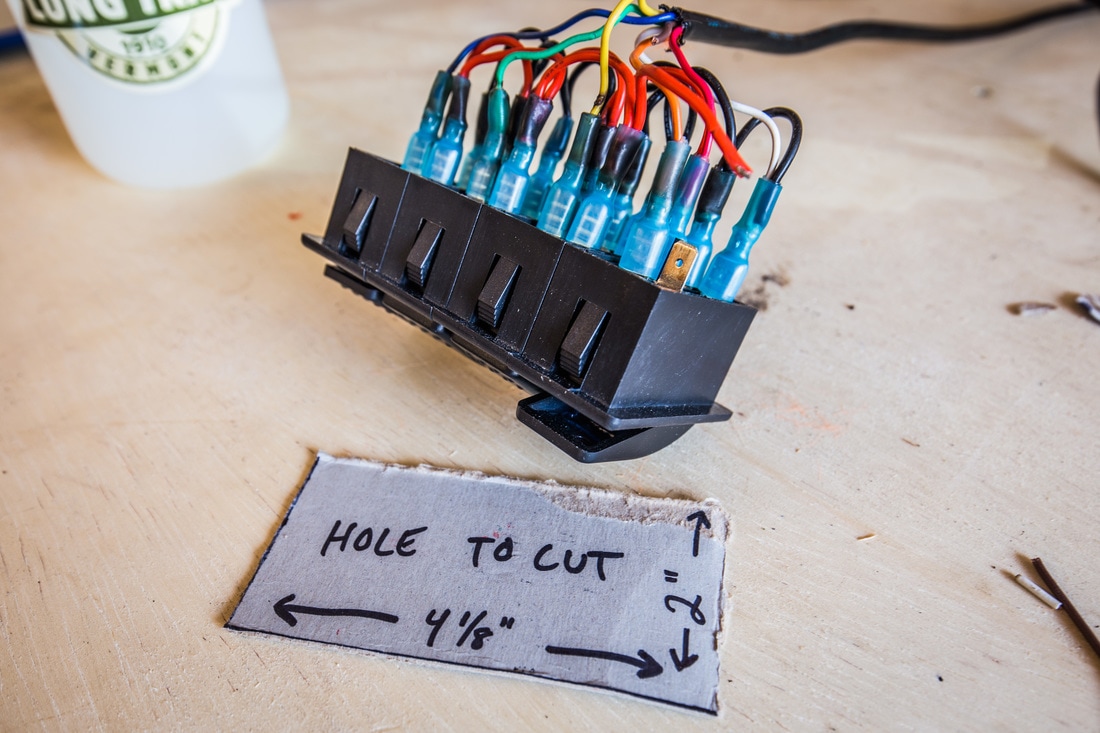
The Contura switches I bought were 5-pin versions… Inputs: +12v for the status light and power source, +12v for the locator light (to find the switch when it’s off), and a ground. Outputs: ground loop, +12v for the light itself. It took some research to find out the exact way to wire this, but once I knew I got to work on an 18awg wire loom for them all. The night I put it together I was sitting in my girlfriend’s office as she worked late and finally had to reassure her coworkers that I wasn’t building a bomb in their workplace. Final results were clean, I was happy.
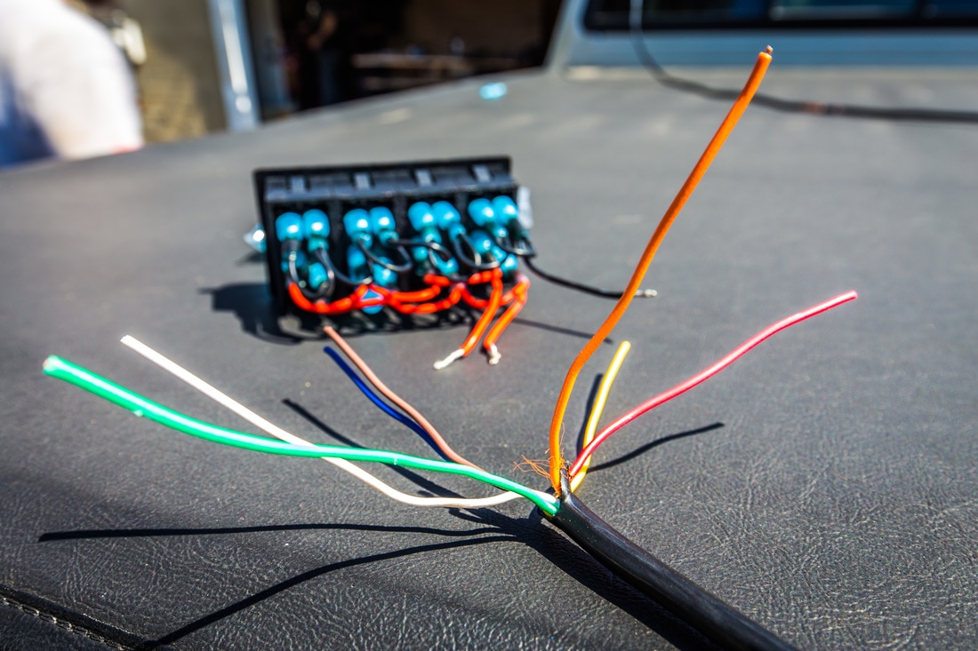
From there I had to figure out what kind of wire loom I would use to get from the eventually-will-be-built control box (relays, fuses, flux capacitors, etc) to the switches. I knew each of the 4 switches would need an individual wire strand to trigger each respective relay, then all would need a +12v lead which they could share, and a ground which they could also share… this brings us to 6-strands of wire for those who can’t count fast.
I work in the live events industry; so 5 and 7 pin cable is a common thing in my life. The issue that I had was the fact that most of those wires, as well as DB9 data cable, are mainly 22-26 AWG, which although it’s okay to push ~0.33A down through, I didn’t want to mess with having to crimp 24 gauge cable to the switch pins. A quick run to Home Depot for 7-strand thermostat cable yielded me a more substantial 7-strand (solid core vs stranded) wire for sprinkler system installations. The other benefit of sprinkler versus thermostat is that the latter was brown, while sprinkler wire housing is black… cleaner to install and easier to hide.
Once I had the wire in hand, I cut each strand to the appropriate length. Red and White would be my hot and ground lines for easy decoding, and the color-coding of the rest would be easy enough to remember for when it’s time to install the control box. In order of (ROYGBIV) I continued past red with Orange on switch 1, Yellow on 2, Green on 3, and Blue on 4. I cut each of the wires to specific lengths to make the sprinkler loom sit cleanly against the switch panel, and then went ahead and crimped/heat shrunk the wires to mate with their female crimp-on ends. I added a separate +12v line made of a miscellaneous five foot section of 14awg wire to tie into an ignition-based +12v line to turn on the locator/indicator LEDs in the bottom of the Contura switches, separate of the ignition.
In laymen’s terms, I wanted the indicator lights to come on with the ignition of the vehicle, but the lights themselves (strobes/rev/LED) to be able to remain on even when the vehicle is turned off. The latter will get their +12v lead from a fuse panel directly tied to the battery.
The result was a rather clean switch panel, parallel grounds and +12v for the leads and switch LEDs, and a 15-foot wire-loom for the relays to be triggered by.

